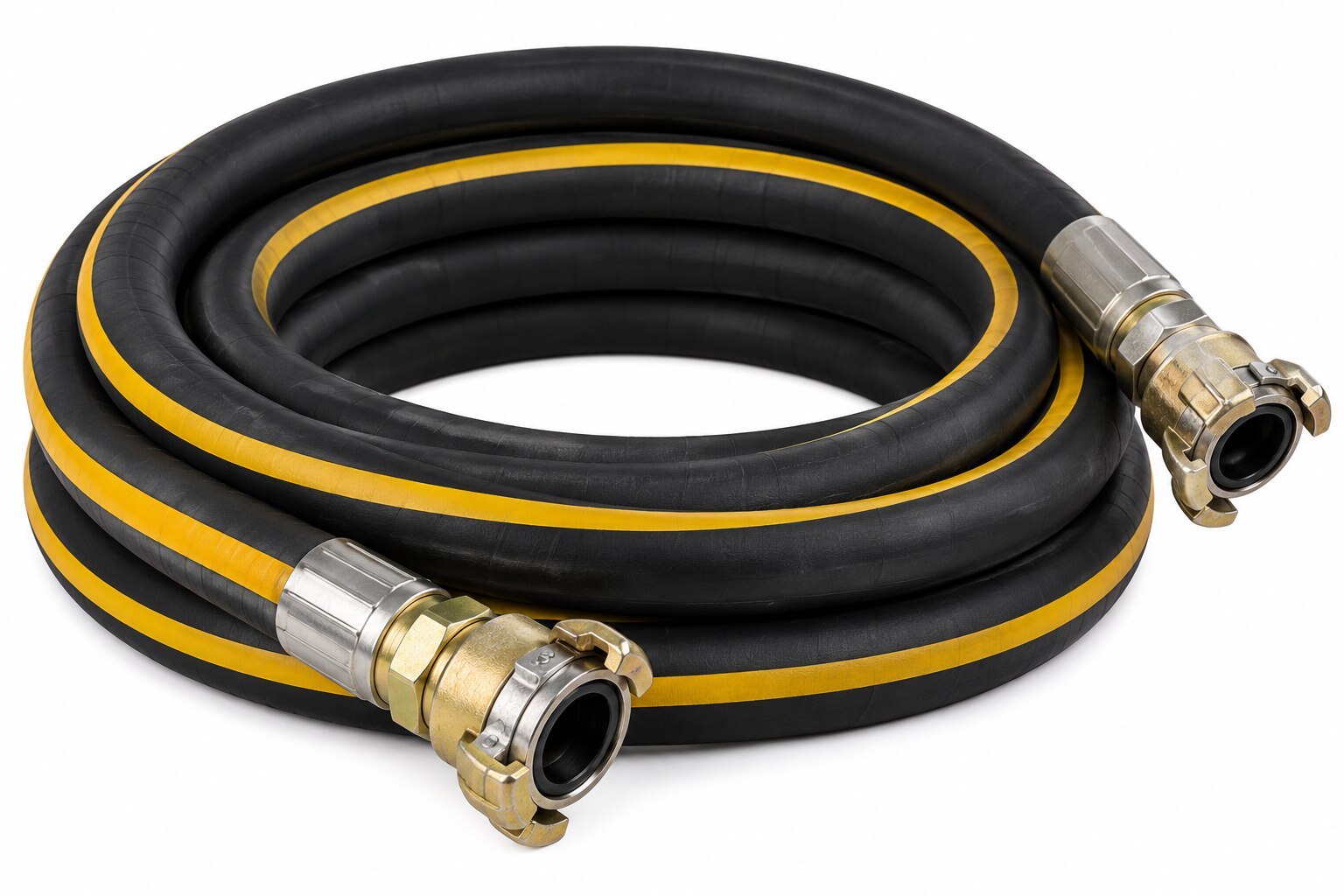
A rock drill hose is part of a high-demand pneumatic circuit, not simply a length of rubber air hose. By mapping the circuit, calculating the required bore and pressure, checking assembly safety, and specifying the right construction and couplings, you can compare quotations without sacrificing drill performance or field safety.
Key takeaways
- Trace the circuit from compressor to drill before specifying hose length or fittings.
- Match hose bore to airflow demand, run length, and connection sizes.
- Check working pressure, pulsation, temperature, and ISO 2398 suitability.
- Specify the complete assembly and inspect couplings, clamps, and hose condition before use.
Map the pneumatic circuit before choosing the hose
A rock drill hose normally carries compressed air from the air receiver or distribution manifold to the drill, with a whip hose providing the final flexible connection at the tool. Trace the pneumatic drilling circuit on site before ordering: compressor, air receiver, isolation valve, hose run, whip hose, drill inlet, and exhaust or blow-down points.
Mark the separate water injection line; a water hose is not a substitute for an air hose.
| Segment | What happens there | Service requirement |
|---|---|---|
| Compressor to air receiver | Air is generated and stored | Check compressor delivery and lubricant carryover; pressure compatibility alone does not prove that the tube tolerates oil-mist air |
| Receiver or manifold to drill | Air travels through the longest run | Select bore from drill consumption, hose length, fittings, and allowable pressure drop; excessive loss reduces impact energy |
| Whip hose at the drill | The hose sees tool vibration, pulsation, flexing, and operator movement | Confirm pulsation and repeated-flex service, secure it with a whip restraint, and choose a tough abrasion-resistant cover |
| Water injection line | Water reaches the drill separately from compressed air | Specify a water-rated hose; suction capability or chemical resistance does not make it suitable for pneumatic service |
A static pressure gauge reading can hide a poor match. The drill creates pulsating demand, so a hose rated for the source pressure can still fail in service if its construction, couplings, or bend radius do not suit vibration and impact. Also verify inner-tube compatibility with compressor lubricant; an oil-resistant cover alone is insufficient.
Size the bore for airflow, distance, and connection fit
Use the drill’s required airflow and allowable pressure drop to choose the hose inside diameter, not the outside diameter or pressure rating alone. A small bore over a long run can starve the drill: compressor pressure looks adequate at the source, but friction loss at the tool reduces impact energy.
Ask the hose supplier to size the nominal bore from these inputs:
- The drill’s air consumption at its operating pressure
- The total hose length and number of bends
- The compressor’s delivered airflow at pressure, not its free-air rating alone
- The maximum pressure drop permitted at the drill inlet
A larger nominal bore reduces pressure drop and preserves airflow, but it adds weight and can make the hose harder to handle. Choose the smallest bore that meets the drill manufacturer’s airflow requirement with the calculated pressure loss, then confirm that the resulting assembly remains practical for the operator.
Check the complete flow path, not just the rubber tube. The smallest passage in a coupling, nipple, safety device, swivel, or drill inlet controls effective flow; a large-bore hose joined to narrow fittings still behaves like a restricted hose.
Match the hose inside diameter and coupling port to the drill inlet, and confirm the connection cannot loosen under pulsating demand.
Do not force the supply hose into a tight bend at the drill. Bending below the stated minimum bend radius can kink the bore, increase pressure drop, and damage the ferrule. A short flexible whip or swivel connection often protects the main hose without requiring a smaller bore.
Compare working pressure, pulsation, temperature, and standards
A hose rated only by its burst pressure has not proved it can run a rock drill. Compare the assembly’s maximum working pressure with the highest pressure at the drill inlet, including compressor surges; the working-pressure figure must remain valid at the actual temperature and duty cycle.
Burst pressure is a destructive-test value, not a permissible operating pressure.
| Check | Figure or evidence to compare | Failure if missing |
|---|---|---|
| Pressure | Maximum working pressure for the complete hose assembly; burst pressure shown separately | Tube rating may exceed a coupling, ferrule, or quick-connect rating |
| Pulsation | Supplier confirmation of pressure pulsation service, repeated flexing, and impact duty | A hose acceptable at static pressure can fatigue under drill demand |
| Temperature | Minimum and maximum service temperatures for the hose, cover, reinforcement, and couplings | Heat near the compressor or cold ground can reduce the stated rating |
| Standard | EN ISO 2398 type, class, nominal bore, maximum working pressure, test pressure, temperature range, and required marking | “Air hose” provides no identifiable performance basis |
Request the rating for the assembled hose, not merely the rubber tube. The lowest-rated component governs. Ask for the EN ISO 2398 designation and conformity or test documentation, then check that the stated temperature range covers compressed air at the hose location, not just ambient conditions.
If the supplier cannot state a pressure-pulsation rating or duty qualification, treat the hose as unproven for rock drilling even when its pressure number appears adequate.
Choose construction and routing for rock, impact, and repeated flexing
Choose reinforcement and routing for the loads that destroy a drilling hose: rock impact, pulsating air, and repeated flexing. Textile reinforcement suits a flexible whip, while wire reinforcement gives greater resistance to pressure pulsation and crushing but adds weight and stiffness. Use the supplier’s stated impact and flexing service, not static pressure alone.
| Option | What it means | When it applies |
|---|---|---|
| Textile reinforcement | Lighter, more flexible construction | Short drill whips and frequent manual handling |
| Wire reinforcement | Higher resistance to pulsation, crushing, and impact | Long runs, severe routing, or heavy-duty drilling |
| Heavy abrasion-resistant cover | Better protection from rock, steel, and dragging | Quarry floors, underground headings, and debris-filled areas |
| Short whip with swivel | Keeps the main hose from sharp bending | At the drill connection and other moving joints |
Make abrasion resistance a specification, not an assumption. A pressure-rated general-purpose air hose can fail quickly after its cover is cut through by rock or rubbed against steel.
Keep every bend above the manufacturer’s minimum bend radius. A tighter bend can kink the bore, increase pressure loss, and load the ferrule; a flexible whip or swivel usually protects the main hose.
For wet, muddy, outdoor, or chemical-exposed sites, require cover compatibility with water, ozone, sunlight, oil, and named chemicals. Fine circumferential cracks in a stretched cover indicate ozone damage.
If electrical hazards exist, specify the required electrical-resistance category, test method, and resistance limit. Verify continuity through the couplings; “anti-static” alone proves nothing. Remove any assembly showing exposed reinforcement, blisters, kinks, coupling damage, leakage, or missing whip restraint.
Specify the complete assembly and verify it before service
Put the complete hose assembly on the purchase order, not just “rock drill hose.” State bore, overall length, maximum working pressure at the actual temperature, pulsation duty, bend radius, electrical-resistance requirement, coupling type, ferrule method, and whip restraint.
1. Check that the working-pressure rating applies to the assembled hose, not only the rubber tube. Treat burst pressure as a destructive-test value, never as an operating limit; the lowest-rated hose, reinforcement, coupling, ferrule, quick-connect, or swivel governs.
2. Compare the smallest passage through the couplings, nipples, safety devices, and swivels with the drill inlet. A large-bore hose still causes pressure loss when a reduced-bore end fitting restricts airflow.
3. Confirm that couplings match the hose construction and that the manufacturer’s specified ferrule or attachment method was used. Reject improvised clamps, mismatched reusable ends, loose threads, and damaged locking sleeves.
4. If static electricity, explosive atmospheres, or mine rules apply, record the required resistance category, test method, and resistance limit. Verify electrical continuity through the couplings; “anti-static” alone proves nothing.
Before connecting, complete a hose inspection for cover cuts, exposed reinforcement, blisters, kinks, leakage, damaged couplings, and a missing whip restraint. Remove any hose with exposed reinforcement or a damaged end fitting; tape and external clamps are not repairs.
Ask Kanta Enterprises to identify the hose, end fittings, pressure rating, and inspection basis on the quotation so you can compare the supplied assembly with the purchase specification before it reaches the drill.
Frequently asked questions
What should you map before choosing a rock drill hose?
Map the compressor, air receiver, isolation valve, hose run, whip hose, drill inlet, and exhaust or blow-down points.
How do you choose the correct hose bore?
Match the internal bore to required airflow, hose length, pressure drop, and the drill and coupling connection sizes.
Which hose performance factors matter in pneumatic drilling?
Compare working pressure, pressure pulsation, operating temperature, burst pressure, and standards such as ISO 2398.
What construction suits rock drilling conditions?
Choose reinforcement and cover materials that withstand abrasion, impact, repeated flexing, crushing, and the planned routing.
What must you verify before putting the hose assembly into service?
Check the hose marking, length, bore, pressure rating, temperature rating, fittings, coupling retention, clamps, and leak-free assembly.