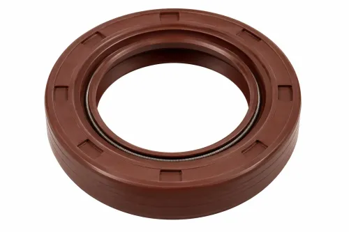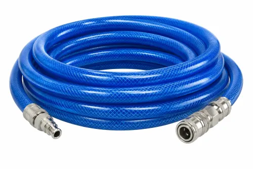
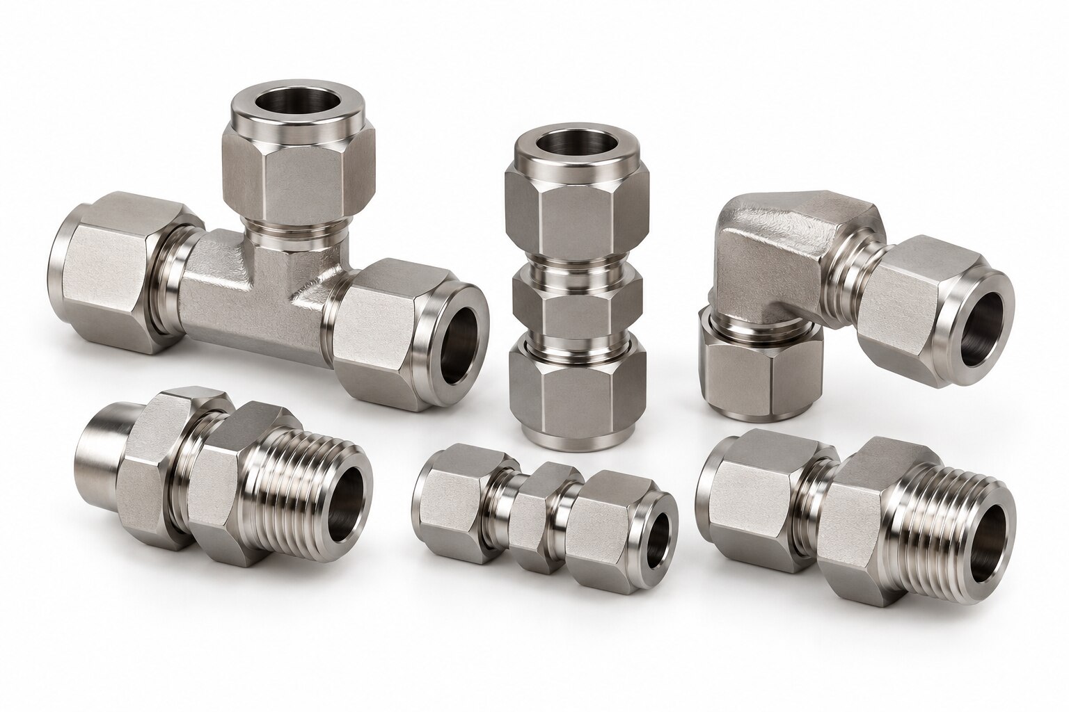
A fitting that appears to match can still fail when its tube outside diameter, thread, cutting ring, material or seal belongs to a different system. By checking the connection in a fixed order, you can identify the correct Ermeto configuration, reject incompatible substitutes and verify that the complete assembly suits its pressure, temperature and installation conditions.
Key takeaways
- Confirm DIN 2353 and ISO 8434-1 before comparing Ermeto fitting dimensions.
- Measure the tube outside diameter and verify thread evidence with gauges or drawings.
- Match fitting materials and ratings to pressure, temperature and fluid compatibility.
- Order the body, nut, cutting ring and tube as one compatible assembly.
Identify the Ermeto fitting system before comparing sizes
Confirm that the assembly is a metric 24° cone system covered by DIN 2353 and ISO 8434-1 before comparing dimensions. An Ermeto tube fitting is not identified by a similar-looking nut or thread alone: the fitting body, nut, cutting ring and tube connection must be designed as one system.
1. Start with marking identification on the fitting body, nut or packaging. Record the manufacturer’s part number, the stated standard, tube outside diameter and series. L series and S series components are not interchangeable simply because their tubes share an outside diameter.
2. Inspect the body shape and sealing end. A conventional fitting has a 24° cone where the tube seals; a port-side version may use an O-ring, bonded seal or specified pipe-thread seal. Do not apply thread sealant to a thread that is not the fluid seal.
3. Match the nut and cutting ring to that exact fitting series and tube size. The ring must have the correct profile and bore for the tube; a ring from another system can bite incorrectly or leave the tube unsecured.
4. Verify the tube connection itself: metric tube outside diameter, suitable wall thickness, material and hardness. Then reject look-alikes such as 37° JIC, flareless, pipe-thread and unrelated compression fittings. They can assemble while failing to seal.
If markings are missing, obtain the maker’s assembly drawing or part-number cross-reference before ordering. Do not identify compatibility from thread size, cone appearance or a replacement nut alone.
Measure the tube and identify the thread from evidence
A 12 mm tube and a 1/2 inch tube are not interchangeable, even when their outside dimensions look close. Measure the tube outside diameter directly; do not select by nominal hose size or pipe size.
1. Measure the tube outside diameter with a calibrated caliper or micrometer at several points around the circumference and along the tube. Record the actual result, not only “12 mm” or “1/2 inch,” because ovality, dents and burrs can distort one reading.
2. Measure wall thickness at the cut end with an ultrasonic gauge or by using a clean, square cross-section. Record the tube material tolerance from its certificate or manufacturer’s data. A cutting ring intended for thin tube can deform it; one selected for thick or hard tube may not form the specified bite.
3. Record the tube material and condition: carbon steel, stainless steel, copper or thermoplastic tube; hardness, annealing state and any coating also matter. Check the fitting maker’s compatibility table before using tube outside its listed range.
4. Identify the port thread from marking or documentation, then verify its major diameter and pitch with thread gauges. Classify it as BSPP, BSPT, metric, NPT, UN or UNF; do not infer the thread from a nut’s appearance. BSPP and BSPT seal differently, and a near-matching thread can damage the port.
5. Note the required tube route and installation space. Measure clearance for the body, nut, spanner and bend radius; a correct fitting can still fail to assemble if surrounding equipment blocks tool access.
Match pressure, temperature, fluid and sealing method
Use the highest real load, not the normal gauge reading, to select the fitting. Compare the manufacturer’s pressure table for the complete assembly at the actual temperature: tube outside diameter, wall thickness, material, L series or S series, fitting body and connection method all affect working pressure.
Include pump pulsation, vibration, accumulator discharge, water hammer and cold-start pressure spikes. The weakest component sets the assembly limit.
Verify these points before approving the selection:
- Check fluid compatibility against the exact fluid, additives and concentration. NBR, FKM and EPDM are not interchangeable; EPDM is generally unsuitable for petroleum oil, while hydrocarbons and elevated temperature may require FKM or another specified compound.
- Confirm the seal’s minimum and maximum temperature, including heat during cleaning, shutdown and pressure cycling.
- Identify where sealing occurs. A conventional 24° connection seals at the tube-to-cone interface through the cutting ring; a port connection may use an O-ring, bonded seal or gasket.
- Apply thread sealant only when the fitting design specifies a sealing thread. Do not add PTFE tape to a thread that seals elsewhere, because loose tape can contaminate valves and restrict the bore.
- Check every adapter, hose and port against the same pressure and temperature conditions. Rate the weakest component, and confirm ISO 19879 qualification where the application requires a tested hydraulic tube connection.
A pressure rating alone does not prove suitability. Confirm the bore, allowable pressure drop, hose bend radius and cleanliness requirement before release.
Check tube preparation, assembly and mechanical loading
Installation starts with a square tube cut, because an angled end prevents consistent cutting-ring engagement. Deburring must remove internal and external burrs without creating an excessive chamfer. Clean all swarf and keep the sealing area free from deep scratches, abrasive grit and oil contamination.
- Push the tube fully against the fitting shoulder before tightening. Mark the nut and body if the maker specifies a torque-turn method; counting turns from the wrong starting position causes both under-assembly and over-assembly.
- Complete pre-assembly in the maker’s hardened tool when required, then perform final assembly in the fitting. Do not substitute a generic wrench procedure for the specified torque or turn value.
- Inspect the ring bite where specified. The ring should show a continuous, even bite around the tube; a partial bite, tilted ring or crushed tube calls for disassembly and replacement, not extra tightening.
- Check tube support and alignment before applying pressure. Support the tube close to the fitting, align it without forcing, and never use the fitting to correct angular or lateral misalignment.
- Add a bend, accumulator or hose section where vibration, pulsation or equipment movement exists. Rigidly loading the connection can loosen it even when its pressure rating is adequate.
- Treat every loosening as maintenance: inspect the tube, cone, nut and ring for scoring or deformation, then follow the maker’s reuse limit. Replacing only the nut will not restore a damaged ring.
- Record the assembly method and inspection result; ISO 19879 provides a recognised test framework for metallic tube connections used in hydraulic fluid-power systems.
Use a final ordering checklist for the complete assembly
Do not release the order until the supplier confirms the complete assembly, not just a catalogue body. A pressure-compatible fitting can still fail if its tube, nut, cutting ring, adapter or port seal belongs to another system.
1. Confirm the fitting part number, tube OD, series, tube material and wall thickness. Make the supplier state whether the combination is L or S series; these are different fitting and tube combinations, not interchangeable pressure labels.
2. Confirm the thread form, thread size and port design. Ask whether the port uses a 24° cone, O-ring, bonded seal or pipe-thread seal, and identify the required seal material. Do not add thread sealant unless the manufacturer specifies it.
3. Request the manufacturer pressure table for the complete assembly. Check maximum steady, transient and cyclic pressure at the actual temperature, including pump pulsation, accumulator discharge and water hammer.
4. Confirm the temperature range, fluid compatibility and cleanliness requirement. Ask whether the supplied assembly meets the required cleanliness level for your hydraulic, gas, chemical or process service.
5. Ask for the internal bore and expected flow restriction. Check pressure drop against the required flow rate, especially where a reducer, small-bore fitting or hose connection creates a bottleneck.
6. Obtain the manufacturer’s assembly instructions, including tube preparation, tightening method and inspection criteria. Confirm the tube hardness limits and minimum bend radius for any connected hose.
7. Request test documentation and the applicable qualification method, such as ISO 19879 for metallic tube connections. Keep the batch or lot traceability with the purchase record.
8. If Kanta Enterprises supplies the connected hose, provide its bore, pressure cycles and bend space so the transition is checked as one assembly rather than as separate parts.
Frequently asked questions
How do you identify an Ermeto fitting system?
Confirm that the assembly is a metric 24° cone system covered by DIN 2353 and ISO 8434-1. Check the fitting body, nut, cutting ring and tube connection as one system.
How do you identify an Ermeto fitting size and thread?
Measure the tube outside diameter, inspect markings and drawings, and verify the thread with a gauge or a known specification rather than relying on appearance.
What operating conditions must you check before selecting an Ermeto fitting?
Match the fitting to working and peak pressure, operating temperature, fluid compatibility and the specified sealing method.
How should you prepare and assemble an Ermeto fitting?
Cut the tube square, remove burrs, keep the tube clean, seat it fully, and follow the specified cutting-ring assembly procedure. Check the finished connection for mechanical loading.